The Fuel Cell
Basic Architecture of a Fuel Cell
Most Fuel Cells have 3 Main layers (figure 1). They are:
1. The Electrode Assembly: This consists of the anode and cathode
2. The Catalyst
3. Other Hardware
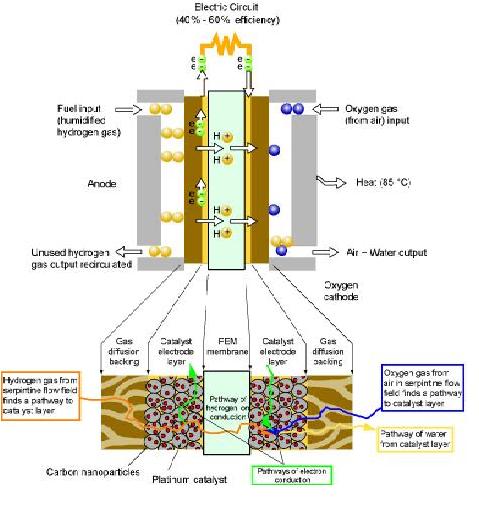
Fig 1: The Fuel Cell
Anode
This is the negative side of the fuel cell. It conducts the electrons liberated from the hydrogen molecules. These electrons flow in the opposite direction to the current that flows through the external load. Channels etched on the anode distribute the hydrogen gas produced over the entire surface of the catalyst.
Cathode
This is the positive side of the fuel cell. It conducts electrons from the external load to the catalyst. These electrons combine with the hydrogen ions and oxygen to form water. The cathode also has channels etched on its surface to distribute oxygen evenly on the surface of the catalyst.
Catalyst
The catalyst is used to coat one side of the electrodes to enable both half reactions (involving the production of water from hydrogen and oxygen) to proceed at a much faster rate at lower temperatures than other electro-chemical conditions. The catalyst used in fuel cells is usually a noble metal, such as Platinum. The use of these noble metals is what makes Fuel cells expensive.
Other Hardware in the Fuel Cell
The backing layers are Teflon coated and positioned next to the electrodes and are usually made of porous thick carbon material. The porous layers guarantee effective diffusion of gaseous molecules to the catalyst on each electrode. They also create a water balance in the fuel cell to prevent the carbon material from getting clogged and reducing the effective gas diffusion (thereby, reducing the reaction rate).
The bipolar plate serves as a flow field and current collector. They are placed on the outer surface of the backing layer. They are made up of lightweight, strong, gas permeable electron conducting materials such as graphite.
The flow fields are etched channels in the sides of the bipolar plate that carry the gases from the entry point in the fuel cell to the exit. The pattern of the field is directly related to the level of distribution of the gases at the electrode assembly.
Each bipolar plate is a current collector. The electrons produced are conducted through the anode, the backing layer and the bipolar plate before exiting the cell. They then pass through the external load as an electric current and re-enter through the cathode.
The Fuel Cell System
Most fuel cell systems have four basic components:
1. Fuel cell stack
2. Fuel cell processor
3. Inverters and Power Conditioners
4. Heat Recovery Systems
Fuel Cell Stack
This is the core of the system; it generates electricity in the form of DC current from the chemical half reactions that occur in the fuel cell. The stack is usually a series arrangement of fuel cells that produce electrical power based on the temperature and pressure of the hydrogen gases supplied to the fuel cell.
Fuel Cell Processor
The processor is usually present in systems that do not employ pure hydrogen for the chemical to electrical energy conversion process. When a hydrogen rich fuel is used such as methanol, a reformer is used to convert the fuel to hydrogen and other carbon compounds called reformate. The reformate is then sent to a reactor where impurities such as SOx and CO are removed to prevent catalytic poisoning. In other cases the high operating temperature reforms the fuel.
Inverters and Power Conditioners
The inverters convert the DC signal from the Fuel cell to an AC signal which is then controlled to match the current, voltage, frequency and signal characteristics of the load.
Heat Recovery Systems
This is used for cogeneration applications. Not all fuel cell systems have this capability. The Solid Oxide Fuel cell system has the ability to generate power at very high temperatures which can be used for CHP.
Challenges
Cost is the primary challenge that Fuel Cell systems face today. At the moment conventional internal combustion systems cost approximately £20/KW while fuel cell system costs range from £700-£1000 for transport and stationary systems respectively.
Durability is also an issue as Fuel cell systems will be required to operate at 40-80 degrees C for transport systems and -35 to 40 degrees C for stationary systems. They must also be able to endure 5000hours (150000 miles) and 40000 hours for transport and stationary applications respectively.
System size is an issue as hydrogen storage and other hardware are very bulky. They must be compressed or configured to meet packaging requirements in vehicles or there will be a huge loss in the drive train efficiency.
Air, thermal and water management are issues because the air management system requires huge compressors and the thermal and water management systems require huge heat exchangers. Future inroads have to be made in research for more compact options to overcome this challenge.
Heat Recovery Systems for cogeneration are not feasible for the fuel cells that have low operating temperatures. Fuel cell systems have to be developed that will operate at high temperatures to harness the CHP potential at high efficiencies.
Fuel Cells for Hydrogen Buffering
In a hydrogen buffering system, a fuel cell is used as an electrochemical device for converting the chemical energy stored in hydrogen into electrical energy when required. The round-trip efficiency (which is a function of the efficiencies of the individual components) of such systems are typically very low (20 – 30%) and have been the major stumbling block against the wide deployment of the technology. The alkaline fuel cell (AFC) is the most developed fuel cell technology and is the fuel cell type chosen for this project. The technical information considered in making this choice as well as the typical characteristics of an AFC is presented.
Types of Fuel Cells
Today fuel cells come in different configurations, operating on different electrolytes and offering a choice of different power ratings, efficiencies and operating characteristics [1]. Different kinds of classification of fuel cells exist but the most common is classification based on the type of electrolyte employed in the cells and includes: Proton Exchange Membrane Fuel Cell (PEMFC), Alkaline Fuel Cell (AFC), Phosphoric Acid Fuel Cell (PAFC), Molten Carbonate Fuel Cell (MCFC), and Solid Oxide Fuel Cell (SOFC). In recent times a new class of fuel cell, known as the Regenerative Fuel Cell (RFC), has appeared on the scene. In general, the operating temperature of a fuel cell is dictated by the type of electrolyte it uses. The operating temperature and useful life of the fuel cell, in turn, determine the properties (physicochemical and thermomechanical) of the materials used in the components of the fuel cell (electrodes, catalysers, interconnect, current collector, etc). Fuel cells which use an aqueous electrolyte have operating temperatures limited to about 200oC or less because aqueous electrolytes rapidly degrade at high temperatures [2]. Table 1 provides a summary of the key features of the main types of fuel cells.
Alkaline Fuel Cell (AFC)
The alkaline fuel cell is undoubtedly the most developed fuel cell
technology and is among the most efficient fuel cells to date. AFCs
produce electricity, water and heat from pure oxygen and hydrogen.
The half-cell reactions are shown below:
The two electrodes in an AFC are separated by a porous matrix (typically asbestos) saturated with an aqueous solution of potassium hydroxide (KOH) which serves as the electrolyte. The pure hydrogen fed to the anode is oxidized by OH- ions arriving from the cathode through the electrolyte. The electrons thus generated migrate to the cathode where the pure O2 fed to it is reduced producing OH- ions.
The AFC typically uses transition metal electrodes loaded with platinum catalyst and are the only class of fuel cells which can achieve efficiencies up to 70%. AFCs have wider operating temperature range (65 – 220oC) compared to PEMFCs and typical energy output is within the range 10 – 100kW.
Fig 3 shows the characteristic linear relationship between rate of hydrogen fuel consumption and the power produced in an AFC. This linear relationship may be represented by the following equation:
In this equation F is the amount of hydrogen fuel consumed by the AFC in kg/hr; Fo is the fuel curve intercept coefficient in kg/hr.kW; F1 is the fuel curve slope in kg/hr.kW; Yfc is the rated capacity of the fuel cell in kW; and Pfc is the electrical output of the fuel cell in kW. The magnitude of the fuel curve slope is an indication of the fuel efficiency of the fuel cell. The smaller the magnitude of the fuel curve slope, the more efficient the fuel cell. It is therefore desirable that this be as small as reasonably practicable. AFCs have the smallest fuel curve slopes of all types of fuel cells and are therefore an attractive prospect because of their relatively high fuel efficiency.
The electrical efficiency of a fuel cell is defined as the fraction of the chemical energy of the fuel that is converted into electrical energy in the fuel cell and may be expressed as:
Where m ̇_fuel is the mass flow rate of the fuel in kg/hr; and 〖LHV〗_fuel is the lower heating value of the fuel in MJ/kg. The factor of 3.6 arises because 1kWh = 3.6 MJ. This relationship may be used to obtain the efficiency curve as shown in Fig 5.
The rate of fuel consumption is related to the fuel curve slope and is given by the following equation:
The smaller the fuel curve slope the smaller the rate of fuel consumption and the more electrically efficient the fuel cell is. Because AFCs have the smallest fuel curve slope of all the fuel cells, they are therefore not only the most fuel efficient but also the most electrically efficient.
Advantages
AFCs are by far the cheapest fuel cells to manufacture. AFCs posses the flexibility to use a wide range of relatively inexpensive catalysts in the electrodes. Its active O2 electrode kinetics gives it an excellent performance on H2 and O2 compared to other types of fuel cells [2]. Since the O2 and H2 for use in the fuel cell can be generated in the electrolyser, AFCs are particularly suited for use in buffering systems for renewable sources of energy. The relatively high efficiency of an AFC helps to increase, albeit only a little, the round trip-efficiency of such systems which are normally very low.
Drawbacks
The sensitivity of the KOH electrolyte to CO2 makes it difficult to use ambient air directly. Some purification of the air is necessary to remove CO2 before it can be fed to the AFC. This adds to both the size and cost of the system. This problem is largely avoided in hydrogen buffering systems for renewables as the H2 and O2 from the electrolyser is sufficiently pure.
Maintenance
The KOH electrolyte used in AFCs readily reacts with CO2, producing potassium carbonate (K2CO3) which considerably reduces the electrical conductivity of the KOH electrolyte. The practice therefore is to include a scrubber which removes the CO2 in the air feed to the fuel cell. The KOH electrolyte also has to be changed from time to time to restore the AFC to its original output. These problems can be largely avoided in hydrogen buffering systems for renewable resources as the H2 and O2 feed are provided by the electrolyser.
References:
[1] Ntziachristos, L., Kouridis, C., Samaras, Z., and Pattas, K., A wind-power fuel-cell hybrid system study on the non-interconnected Aegean Islands grid, Journal of renewable energy, 30, (2005), 1471 – 1487.
[2] Fuel Cell Handbook, Seventh Edition, EG & G Technical Services Inc.
[3] http://www.eere.energy.gov/hydrogenandfuelcells/fuelcells/fc_types.html)
[4] www.fctec.com/fctec_types_afc.asp